September 21, 2008 - Brake Lines, Lightspeed Wiring
|
|
I finally got
around to putting in the brake lines that run from the firewall (forward
side) down the gear legs to each brake assembly. The bends look very
fancy but they were easy to
do. |
|
|
|
|
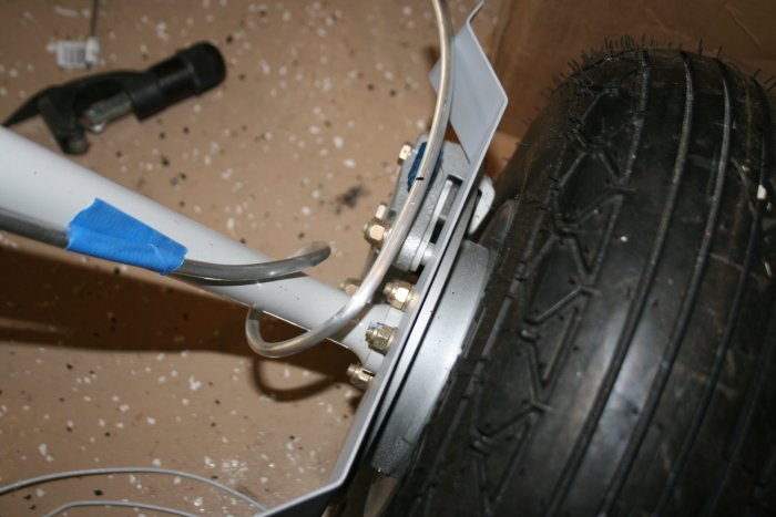
Per the drawings, I ran them down the
front of the gear legs and then made a 360 degree wifferdil around the
gear to the top of the brake assembly.
|
|
|
|
|
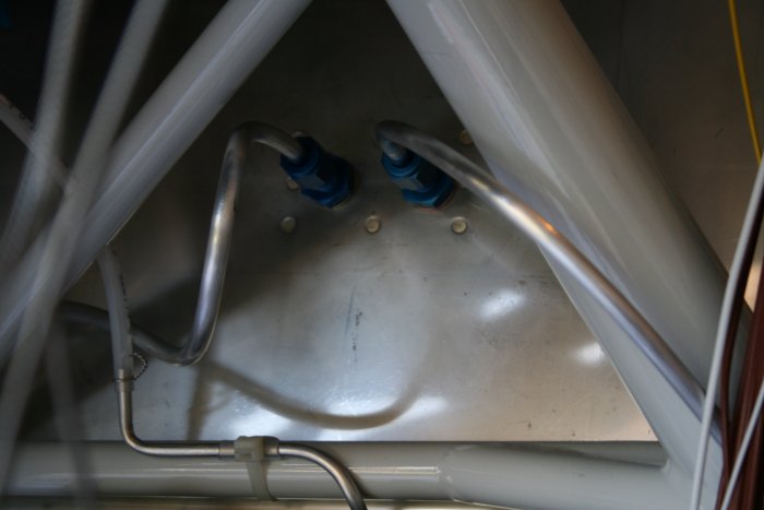
I installed the AN
fittings, then put clear plastic around the tubing in three places and
taped the tubing to the gear leg with black electrical tape. All
exactly per the drawings. |
|
|
|
|
I ran out of 1/4" inner diameter
tubing so I'm on hold with the right side. Plus I have to secure the
tubing to the engine mount with adel clamps.
|
|
|
|
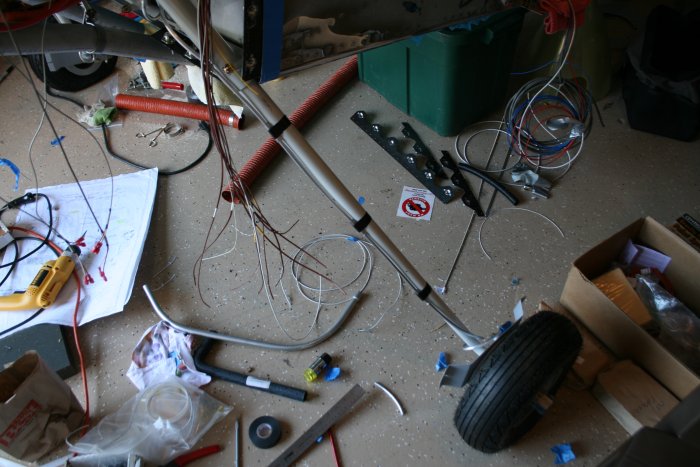
| I'm trying to
figure out how to run my ignition, EGT/CHT sensor wires, and Lightspeed
sensor wire. I used tie-wraps to experiment with different
runs. |
|
|
|
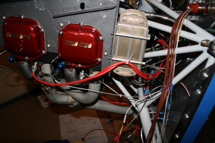
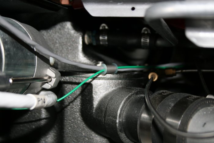
| I secured the
Lightspeed sensor wire and green Alternator-Voltage Regulator to the
engine. |
|
|
|
|
The right side of
the engine. |
|
|
|
|
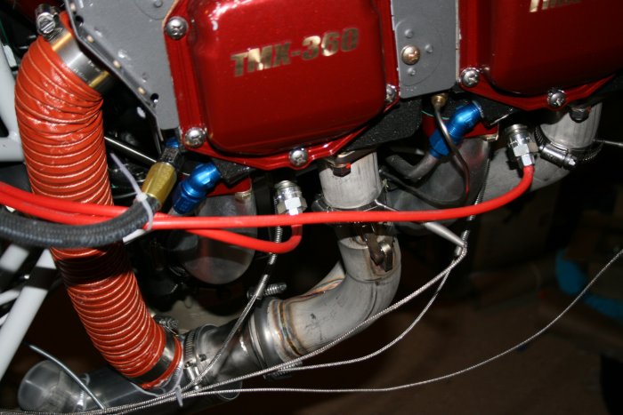
Finished hooking up the Lightspeed
ignition wires to the coils.
|
|
|
|
|
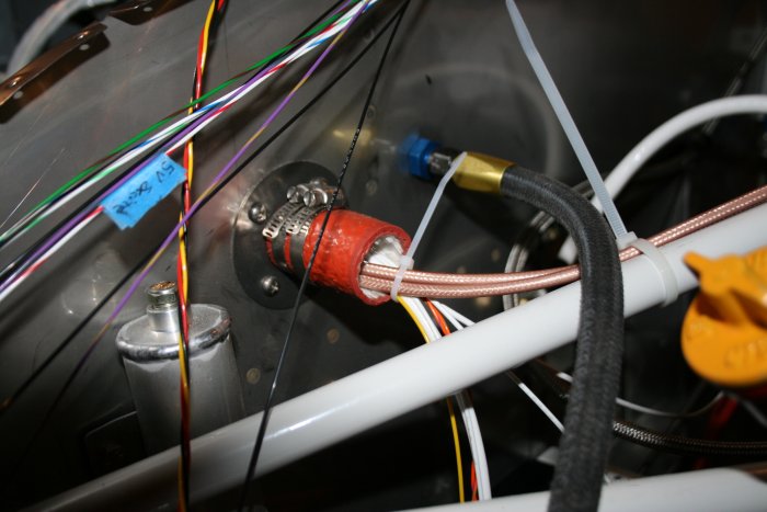
The Lightspeed
ignition wires run through the firewall on the right side. I tried
to route all my power and ignition wires on the right side, sensor wires
on the left. |
|
|
|
|
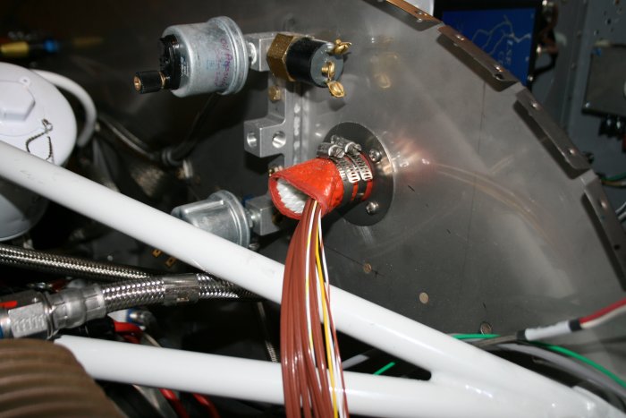
Speaking of the left side, here it
is. All the sensor wires go through here: EGT, CHT,
Lightspeed, oil pressure, oil temp, fuel pressure, and fuel
flow.
|
|
|
|
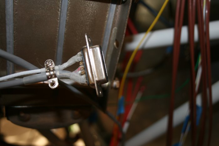
| The is the end of
the Lightspeed sensor wire. The famous issue with this is how to get
that 15-pin connector through the firewall hole. My decision was to
cut off the connector, run the wire bundle through the firewall hole, then
put a new 15-pin connector back on. But instead of soldering, I
would use D-Sub pins. |
|
|
|
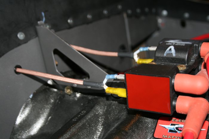
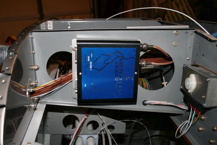
| The Lightspeed
brainbox where the 15-pin connector attaches (on the left). You can
see the two ignition wires coming in on the right side of the
brainbox. |
|
|
|
| |
|
|
|
|
|
|
|