June 16, 2004 - Left Wing Nutplates
It may seem as if I havn't done anything since June 6, but I have. Really. The elevator trim tab is on hold until the extra flush pop-rivets I ordered from Van's arrive. So I decided to start on the Wings. The first item on the instructions is to install nutplates on the wing spar. One paragraph. 10+ hours of work.
I started Sunday by looking at the plans. Before I started drilling into a piece of aluminum that is the key structural component of the airplane and probably cost over $1,000, I wanted to be sure I knew what I was doing. I just wasn't getting it from the plans, I went upstairs and checked out Dan Checkoway's and Todd Moeller's websites. Then I went and looked at the plans some more. After I felt like I understood what to do, I made an aluminum angle guide and a testing device. Then I countersunk one big hole. And that was it for Sunday -- 3 hours work. One countersunk hole. 129 to go.
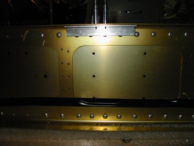
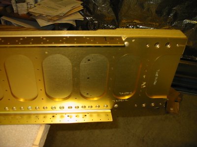
Here is the inboard end of the left wing spar, as it comes from the factory. The workmanship is outstanding. It is not made of gold, but it is annodized for corrosion protection.
On Monday I went to the local EAA Chapter meeting and learned about the new Deltahawk Diesel engine. I was impressed. If Van's is selling this engine by the time I'm ready to buy the powerplant, I might just get one.
I was starting to receive intense pressure to get those big crates out of the basement, so Tuesday evening, I spent over an hour taking apart the wing kit crates and sawing them in pieces small enough to fit into the minivan for a trip to the dump.
Wednesday evening, I was able to get back to some real airplane building. My goal was to rivet all 30 nutplates on the top left spar.
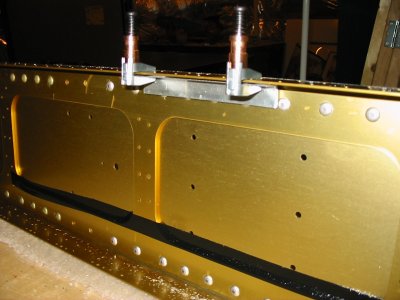
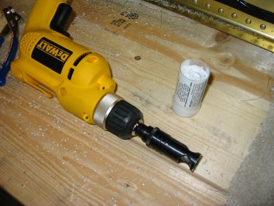
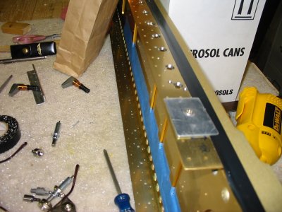
These nutplates allow the fuel tank skin to be fastened down with #8 screws. There are 30 nutplates on the top spar flange, 30 on the bottom. The skins are dimpled so the #8 screws will end up flush. That means the spar has to countersunk so that the skin rests tight to the spar flange. I'll use my countersink bit for #8 screws, with a #19 guide.
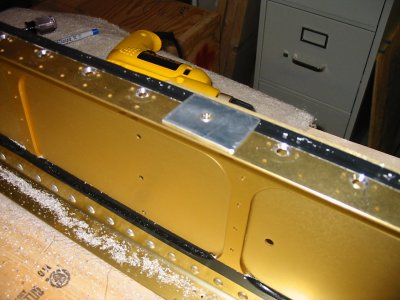
Due to the flange thickness, or lack of it, the countersink bit makes a bigger hole than the #19. I used Dan Checkoway's technique and fashioned a guide of aluminum angle. First I cleco it to the bottom of the flange using the rivet holes on each side of the #8 screwhole.