July 15, 2007 - Panel: Switch Holes

The next step was to drill the screw holes for the two round instruments.  Instead of backdrilling, I just marked with a Sharpie where each hole should go and drilled it from the front.  I had to do a little filing with the needle file but not much. 
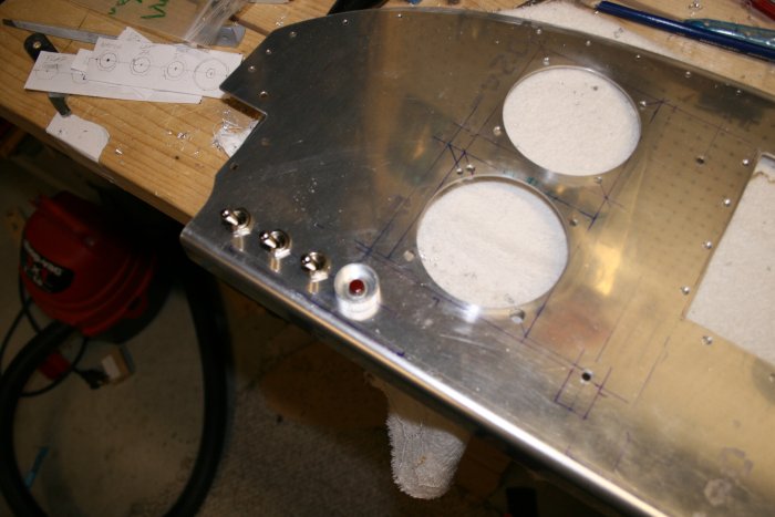
With the round holes done, I turned my attention to the switches, Starter button, circuit breaker and indicator lights.  I did some more research and planned exactly what would go where.  I have most of the stuff on hand but I need one more switch and two LED indicator lights.  I think I'm just going to pick these up at Oshkosh when I'm there next week. 
I liked the way Dan Checkoway did his switch holes so I followed his example.  I made a 1" backing strip of .063 aluminum and drilled two #30 holes for each switch -- one for the center of the switch, and one for the locking washer.  Then I backdrilled the strip to the panel. 
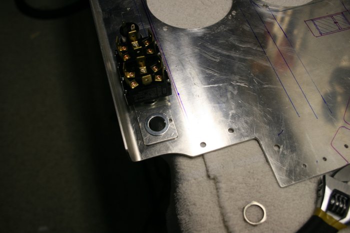
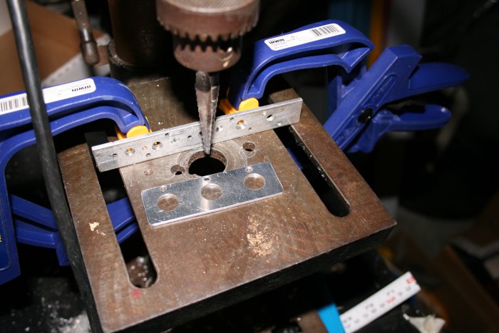
Next I drilled out the center holes on both the backing strip and the panel to 7/16", using my Unibit. 
I started with the left-most switches, which are Master, Left Ignition, Right Ignition and Start button.  They came out in a nice straight row.

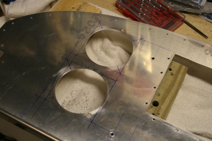
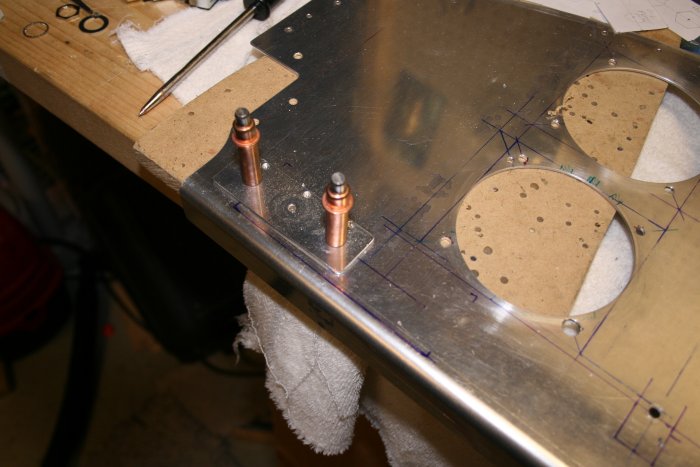
You may have noticed I made a mistake on the Pictorial Pilot mounting holes.  I drilled a hole in the wrong place.  I drilled a second hole in the right place.  I'm going to fill the wrong hole with epoxy or JB weld.  Once the panel is painted, it won't be visible.

Looking at the switches from the rear. 
This picture shows how the locking washer fits into the hole on the backing strip, preventing rotation of the switch. 
Previous
Home
Next