October 10, 2006 - Electrical System
|
|
The Bible for all things electric in experimental airplanes is
The AeroElectric Connection by
Bob Nuckolls. I'm not going to say I understand the entire book, but
I can say my understanding of aircraft electrical systems has improved by
an order of magnitude. You can cut to the chase by going directly to
Chapter 17 "Electrical System Reliability". The book has lots of
suggestions and recommendations. The part I liked best was
Appendix Z which contains power distribution diagrams. For my RV-7,
I decided to go with Figure Z-11 which "depicts a single-battery,
single-alternator architecture useful on about 90% of the airplanes being
built."
I did the electrical system in our Citabria restoration so I have
something to relate all this too. My RV-7's electrical system will
be far superior to what is in the Citabria.
If your building an airplane, this book is a must-have. |
|
 |
|
I decided to start ordering stuff for my electrical system. I'm
buying most of the components from B&C
Specialty Products and most of the wire from
Stein Air. B&C isn't the
most inexpensive way to go but I felt they offered the highest quality.
Some of these components like the alternator and contactors come in
Van's Firewall Foreword Kit but I think you can have the left out.
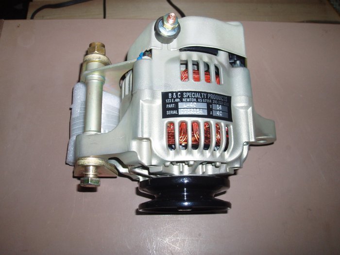
The key component of the system is obviously the Alternator. I
went with the B&C 40A alternator, boss mount. It's made from all
new parts and has a dynamically balanced rotor.
My airplane will be all-electric. I want a reliable electric power
source so I'm splurging a little in this area.
|
|
 |
|
|
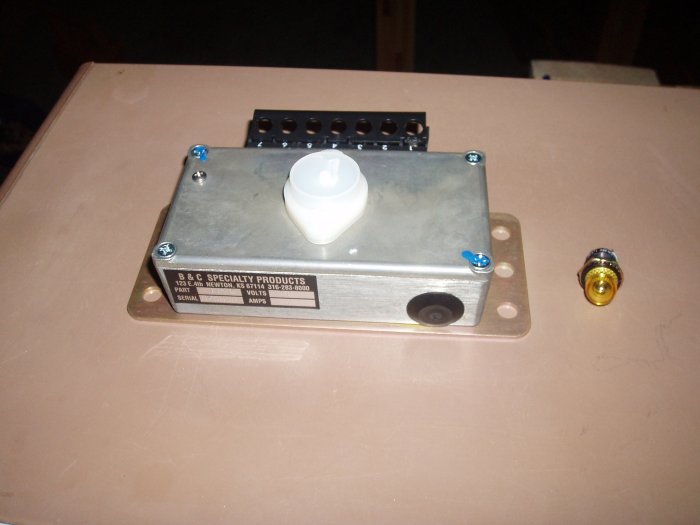
This is the B&C LR3C-14 Controller which acts as a regulator, protects
from over voltage, and monitors and warns against low voltage.
That's the low voltage warning light to the right. |
|
 |
|
|
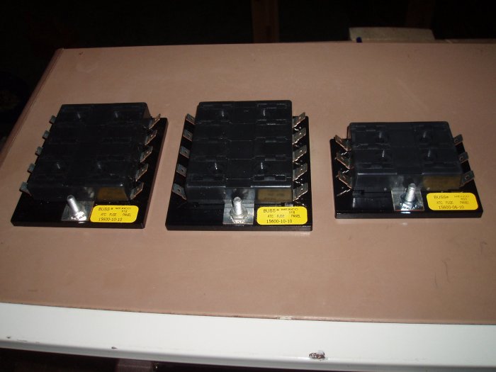
These are the fuse blocks, one for each bus: Main (10), Essential
(10) and Battery (6).
|
|
 |
|
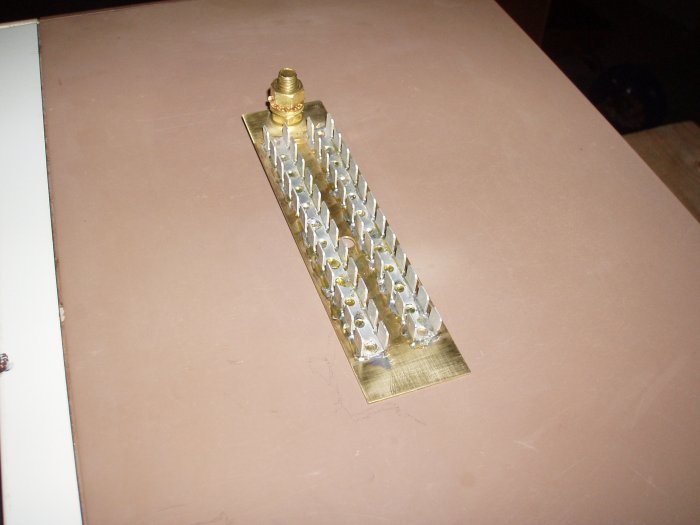
| This is the 48-port Ground Bus
which will attach to the firewall. There will be very few local
grounds in my system; almost everything will ground to this one bus. |
|
 |
|
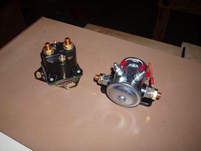
| The Starter and Battery Contactors. |
|
 |
|
|
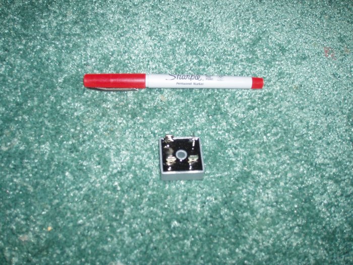
The diode that will ensure current only flows one way between the Main Bus
and Essential Bus. |
|
 |
|
|
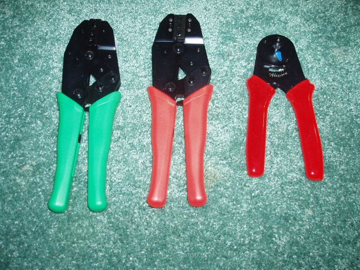
Three crimping tools for coax, regular wire connectors, and D-pins.
|
|
 |
|
|
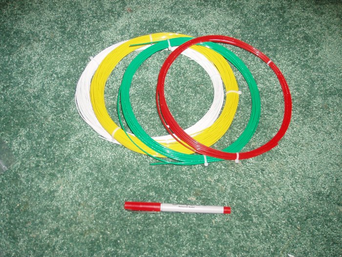
I ordered the wire from Stein Air. Initially I thought about making
each system a different color but I would have had to estimate how much
wire each system would use. Too hard. I decided to just make
each wire size a different color: white (22), yellow (20), green
(18) and red (16). I thought red for 16 was nice because 16 goes
between the buses. At least according to diagram Z-11. |
|
 |
|
|
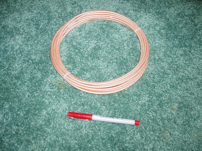
Coax cable.
|
|
 |
|
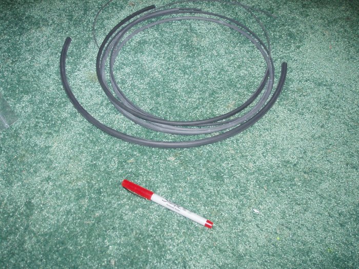
| Heat shrink of various sizes.
After you crimp the connector to the wire, you shrink this stuff over it. |
|
 |
|
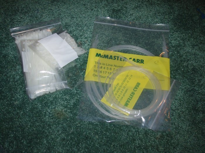
| I decided to do what Dan Checkoway
did as far as labeling the wires. You make the labels with the word
processor at #6 size, then heat shrink clear tubing over it. I ordered
the clear from McMaster Carr. I
ordered it one day and it arrived the next. Awesome service. |
|
 |
|
| |
|
|
|
|
|
|
|